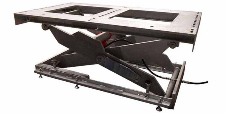
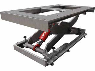
The lift table in the image is used by a renowned gearbox manufacturer to test assemblies. What is special about this is that the tests are carried out under water! Accordingly, the scissor lift table is also completely under water at times. Read below how the design was prepared for these harsh operating conditions.
The lift table pit is usually designed with a slight slope and a drain to protect the scissor lift from permanent wetness as much as possible. This project is different. Contact with water cannot be avoided, especially since the entire lift table (and not only parts of it) is completely submerged at times.
Using a stainless-steel lift table would be optimal to guarantee many years of operation. However, as lift tables made entirely of stainless steel are comparatively expensive (at least twice the price of a lift table made of steel), this solution was out of the question. So, a different concept was needed. In the following section we will explain what we have done to make long-term operation in these conditions possible.
The surface protection
Whenever there is a risk of a component coming into contact with water for a longer period of time, as is the case with an outdoor lift table, the corresponding module will be hot-dip galvanised. This surface protection is distinguished by its very high resistance to mechanical stress and adverse environmental influences. However, this usually only affects the platform and the base frame and not the entire lift table as in this case.
The fact that the scissors of the lift table also had to be hot-dip galvanised is not entirely unproblematic from a manufacturing point of view, as a comparatively large volume of welding is carried out in the scissors. This results in high temperatures and internal stresses. These stresses are reduced during hot-dip galvanising, which is equivalent to a warping of the component. But warping of the scissors in a lift table cannot be tolerated, though.
This makes it important that the following points must be observed both during the design and production of the scissors:
- Avoidance of hollow parts
(in the worst case these could lead to bursting of the corresponding component when heated) - Reduction of welding stresses through:
- a design with as few welds as possible,
- avoidance of "weld seam accumulations" and
- an extended cooling phase after the welding process.
As the successful commissioning of the galvanised scissor lift table shows, these measures prevented the scissors from warping.
The drive train
A great advantage of hydraulic scissor lift tables is the possibility of setting up the drive unit and the lift table spatially separated from each other. In this application, too, the power unit was installed outside the lift table to avoid the harmful influence of water.
But even if the electric motor, the pump and the valves are located outside the water, there are unfortunately still components which are not so easy to protect.
These include, for example, the hydraulic cylinders. Naturally, they must be installed inside the scissor structure for them to perform properly. To increase the resistance of the cylinders to the water, special cylinders were used. In contrast to standard cylinders, these have a nickel-plated and triple chrome-plated piston rod as well as special seals for the HFC fluid used.
Like the hydraulic cylinders, the hydraulic hoses are also submerged at times. To handle this situation, hoses made of fabric material with stainless-steel fittings were installed.
As already mentioned, the lift table is operated with HFC liquid. HFC liquid is characterised by a high water content and low flammability. However, this also prevents the use of the under-oil units that we prefer. The high water content in the pressure medium would cause a short circuit of the rotor winding. For this reason, we have made use of a compact power unit in this project, as is also used by a large part of the other lift table manufacturers.
The mechanical components
If you look at the pictures, you will soon notice that the platform is not completely closed. Instead there is an open platform frame above the scissors.
This is easy to explain. A closed platform would have one major disadvantage when the lift table is lowered – it would float. To prevent this, large openings were cut in the platform to allow the water to flow through. The substructure and the sheet thickness were reinforced to still ensure sufficient rigidity.
If you take another closer look at the platform, you will also see a whole series of slotted holes. Unlike the open platform frame, they are not intended to counteract the buoyancy of the water. The slotted holes are there at the customer's request. The customer uses them to install a large number of different tool heads on the platform and are therefore very flexible in the test setup.
Of course, other special features were also built into the lift table. However, we do not want to go beyond the scope of this article, but only show that underwater use of a hydraulic lift table is theoretically and practically possible.


