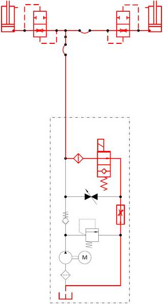
In this article you will find a hydraulic diagram for a single hydraulic scissor lift table. Besides the electrical diagram and the production drawings of the lifting mechanism, this is one of the most important components you need to build a lift table yourself.
Please read through the whole article before you start to build the hydraulic circuit. In the course of this article we will describe how the different operating states are implemented with the aid of the hydraulic circuit and what function the different components perform.
Structure of the lift table
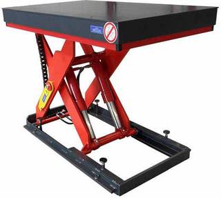
The diagram provided here is suitable for a single hydraulic standard lift table with a standard structure of base frame, scissor lift mechanism and platform. Single-acting hydraulic cylinders are used, i.e. the cylinders are moved together again by the load to be lifted and the weight of the platform. It may be necessary to use double-acting cylinders for small loads to be lifted or a scissor lift with a lightweight structure. However, this configuration is not possible with the 2/2-way valves listed here.
Operating states of the lift table
We don't just want to provide you with a hydraulic diagram for a lift table, but we also want you to understand what exactly happens to the hydraulics in the various operating states and how a hydraulic lift table actually works.
To keep it as simple as possible, you will find numbers after the various components in the description text. These refer to the item numbers in the hydraulic diagram. It is therefore advisable to print out the hydraulic diagram first and to follow the procedure parallel to the description using the plan.
Normal operation
When used in normal operation, our lift table should do nothing more than lift or lower a load. This simple function can already be implemented with the help of a few components.
Lifting movement
The hydraulic cylinders (No. 1) must extend for the platform of the lift table to be raised. This means that their chambers must be filled with oil. This is done by the hydraulic pump (No. 10), which in turn is driven by an electric motor (No. 11).
Accordingly, all valves are in their initial position during the the lifting movement and do not have to be actuated. The electric motor (No. 11) is turned on and drives the hydraulic pump (No. 10). The volume flow of the hydraulic pump now flows from the pump via the hose line (No. 3) into the hydraulic cylinder (No. 1). As soon as the desired position has been reached, the electric motor is turned off again and the pump no longer provides the volume flow. The check valve (No. 8) prevents the hydraulic oil from flowing back into the tank. This is necessary to prevent the platform of the lift table from lowering again.
Lowering movement
For the platform of the lift table to lower again, the hydraulic oil must flow from the cylinders (No. 1) back into the tank. This is achieved by operating the lowering valve (No. 6).
The lowering valve (No. 6) is normally closed (NC). This means that no hydraulic oil flows through the valve when it is not actuated. This can be identified by the small check valve on the side of the spring of the corresponding symbol. When the coil of the hydraulic valve is supplied with voltage, the valve opens. Oil can now flow from the hydraulic cylinders (No. 1) through the lowering valve (No. 6) back into the tank and the platform of the lifting table lowers.
To keep the actuation of the valves as simple as possible, no proportional valves were used. The installed valves only know two states: open and closed. Without additional components, the lowering speed of the platform would vary greatly depending on the ambient temperature and the load. That is why there is a lowering brake valve (No. 5) before the lowering valve (No. 6). It limits the volume flow during the lowering process and so prevents the lift table platform from being lowered too quickly.
Senkbewegung
Damit sich die Plattform des Hubtisches wieder senkt, muss das Hydrauliköl aus den Zylindern (Pos. 1) zurück in den Tank fließen. Dies wird durch die Betätigung des Senkventils (Pos. 6) erreicht.
Das Senkventil (Pos. 6) ist stromlos geschlossen. Das bedeutet, dass kein Hydrauliköl durch das Ventil fließt, wenn es nicht betätigt wird. Erkennbar ist dies an dem kleinen Rückschlagventil auf der Seite der Feder des entsprechenden Symbols. Wird die Spule des Hydraulikventils mit einer Spannung versorgt, öffnet sich das Ventil. Nun kann Öl von den Hydraulikzylindern (Pos. 1) durch das Senkventil (Pos. 6) zurück in den Tank fließen und die Plattform des Hubtisches senkt sich.
Um die Ansteuerung der Ventile möglichst einfach zu halten, wurden keine Proportionalventile verwendet. Die verbauten Ventile kennen nur zwei Zustände: offen und geschlossen. Ohne weitere Bauteile würde die Senkgeschwindigkeit der Plattform in Abhängigkeit von der Umgebungstemperatur und der Last stark variieren. Daher findet man vor dem Senkventil (Pos. 6) noch ein Senkbremsventil (Pos. 5). Dieses begrenzt den Volumenstrom während des Senkvorgangs und verhindert somit ein zu schnelles Absenken der Hubtischplattform.
Faulty operating state
Even though this hydraulic diagram is intended for a simple, robust lift table, malfunctions may occur during operation. There are usually only two faults that can occur in such a simple lift table. The lift table's hydraulic line is ripped or the lift table's control system has failed (solutions for other faults can be found in this article). Safety measures have been included in the hydraulic diagram for both faults, which will now be described in more detail.
Break or rupture of the hydraulic line
The hydraulic line can break or rupture for a variety of reasons. For example, a hydraulic hose should be replaced after seven to eight years at the latest, as it becomes brittle over time and can then no longer withstand the operating pressure. Other frequent causes of such a fault are incorrect assembly or a material defect in the components used.
If the hydraulic line breaks or ruptures, it must be ensured that the platform and consequently the load to be lifted do not drop uncontrollably.
In this case, it is prevented by pipe rupture safety valves (No. 2). They are installed directly on or in the hydraulic cylinders (No. 1) and close the hydraulic line if the pressure difference is too great. After such an event, the faulty supply line must be repaired and the lift table slightly raised again. The brief lifting motion is necessary to eliminate the pressure difference between the two sides of the pipe rupture safety valve and so reopen the safety valve.
It is important to know that a pipe rupture safety valve does not detect all damage to the supply line. For example, a small leak in the supply line does not lead to a large pressure difference and therefore does not trigger the pipe rupture safety devices. It may therefore be necessary to use other safety valves. A list and explanation of possible alternatives can be found in this article.
Power failure or electrical fault
The lowering valve (No. 6) in the hydraulic diagram is actuated by an electric coil. A power failure or a fault in the control system could make it impossible to lower the load. An emergency release valve (No. 7) is installed parallel to the lowering valve (No. 6) to allow the lowering of the load in an emergency. This can be operated manually in case of damage and allows the hydraulic oil from the cylinders (No. 1) to flow back to the tank via the hose line (No. 3) and the lowering brake valve (No. 5).
Function of the installed components
In this section we give a concise explanation of the function of the various components of the hydraulic circuit.
No. 01: Hydraulic cylinder
The extension movement of the hydraulic cylinders pushes the scissor halves apart and so generates the lifting movement of the lift table. The retraction of the hydraulic cylinders lowers the platform.
No. 02: Pipe rupture safety valve
It closes off the hydraulic line in case of a sudden hose or break in the pipeline. This prevents the lift table platform from dropping in the event of damage.
No. 03: Hydraulic hose
This is a flexible hose connection between the valve block of the drive unit and the hydraulic cylinders. This flexibility is necessary to compensate for the movement of the scissor lift mechanism.
No. 04: Measuring connection
The valve block should have a measuring connection for checking purposes. This makes it possible, for example, to monitor the existing pressure during the lifting process.
No. 05: Lowering brake valve
It ensures the smooth lowering movement of the lift table platform regardless of the load..
No. 06: Lowering valve
When activated, this valve allows the platform to be lowered.
No. 07: Emergency lowering valve
It enables the platform to be lowered in the event of a power failure or a fault in the control system.
No. 08: Check valve
It prevents the hydraulic oil from flowing back into the tank and so holds the platform of the scissor lift table at the desired level.
No. 09: Pressure relief valve
When open, this valve directs the volume flow into the tank. It opens when the pressure in the hydraulic circuit is too high, thus protecting the hydraulic components as well as the mechanical structure against unacceptably high loads.
No. 10: Hydraulic pump
It pumps the hydraulic oil into the cylinders and so enables the lifting movement of the lift table.
No. 11: Electric motor
It drives the hydraulic pump.
No. 12: Filter
It protects the installed hydraulic components against dirt particles and the usual abrasion in hydraulic oil.
No. 13: Filler neck
To fill the tank with hydraulic oil.
No. 14: Oil drain
To drain the hydraulic oil, for an oil change, for example.


Comments (0)
No comments found!