Despite all the differences, wheel loaders in road construction, dumpers in transport or hydraulic clamping devices in machining centres have one thing in common: they all use hydraulic cylinders to exert high forces. In this article we would like to explain how to select the right hydraulic cylinder.
Selection criteria
In the selection criteria, we would like to limit ourselves to the essential parameters of a hydraulic cylinder . Your cylinder manufacturer will ask you more questions with regard to your enquiry, for example about the desired connection thread, the operating temperature or similar.
Single-acting or double-acting?
A distinction is made between single and double-acting hydraulic and pneumatic cylinders. Single-acting cylinders have one active direction of movement, while the double-acting cylinder can be moved actively in both directions . What is meant by this? Let us take a tipper as a typical example of a single-acting cylinder. A tipper is a special type of truck trailer that is able to unload loads (e.g. gravel) at the place of use by tilting the cargo bed.
With a tipper, a high load must be lifted so that it can slide off the cargo bed due to the tilt of the cargo bed. This means that a very large force is required to lift the entire load. This is achieved by applying pressure to the piston side of a hydraulic cylinder. The cylinder extends and tilts the cargo bed. No active movement is required to retract the cylinder, i.e. the hydraulic power unit is not turned on for the retraction. The dead weight of the cargo bed is sufficient to allow the cylinder to retract. This means that hardly any energy is required during the lowering movement, simply opening the lowering valve is all that is needed.
In contrast, double-acting cylinders are used when active movement in both directions is required. A typical example is the steering axle of a wheel loader. Let us assume that the wheel of the wheel loader turns to the right when pressure is applied to the piston rod. Now there is no external force that would cause a counter movement. Instead, pressure must be applied to the ring side of the hydraulic cylinder to retract the cylinder and cause the wheel to turn to the left.
Force required
Another important parameter is the force to be applied by a hydraulic cylinder, i.e. for the respective application it must be determined which force is required for the active movement. In conjunction with the maximum buckling force and the permissible operating pressure, the force to be applied can be used to determine the required piston diameter. We will go into this point in more detail in the following practical example.
Effective stroke required
The effective stroke is the difference between the retracted and extended position. Depending on the application, the effective stroke can range from a few centimetres to several metres. This variable is determined by the geometrical conditions of the design.
The installation length of the cylinder is largely determined by the effective stroke of the hydraulic cylinder. The installation length can be calculated using the effective stroke and the zero length of the cylinder. The zero length describes the length of a cylinder without effective stroke, i.e. this measurement includes the necessary length for the guide bands, the connection, etc. The zero length is usually obtained from the cylinder manufacturer depending on the piston diameter, the connection type and the cylinder design. The installation length is then calculated from the zero length of the respective cylinder and the effective stroke of the cylinder.
Practical example: single scissor lift
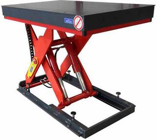
It will probably not surprise anyone when we use a scissor lift table as a practical example for the selection of a hydraulic cylinder. To keep it as simple as possible, we will use a single scissor lift table without any additional functions , i.e. the lift table only has a lifting and lowering function and no other extras such as a tilting device or a powered rotating platform. So let's get started:
The type of cylinder
We only use single-acting hydraulic cylinders for the lifting and lowering function of our scissor lift tables. The solid structure and the associated dead weight of the platform and the scissors ensure that the cylinder retracts automatically. This means the hydraulic unit only needs to be activated during the lifting operation. For the downward movement we simply open the lowering valve and the cylinder is compressed again by its own dead weight. If you want to know more about how a scissor lift table works and how the hydraulics are controlled, you will find the information here .
Effective stroke required
As already mentioned above, the required effective stroke is derived from the geometrical conditions at the place of use. The objective of every lift table manufacturer is to achieve a pressure curve that is as constant as possible .
The pressure curve in is turn influenced by the ratio of the lever arms of the load and the lever arms of the hydraulic cylinders. By taking the installation length of the hydraulic cylinder and the lever arm ratios into account, we have determined the following sizes for the selection of the cylinder:
- Retracted length of the cylinder = 516 mm
- Extended length of the cylinder = 767 mm
- This results in an effective stroke of 251 mm
Operating pressure or buckling
The geometric conditions not only determine the necessary effective stroke, but also the necessary force of the hydraulic cylinder. In a scissor lift table, the load acts on the hydraulic cylinders via the scissor bars and the cylinder mount shafts. The lever arm ratio determines the compressive force required to extend the cylinders and lift the load. If the force is known, the necessary piston diameter of the cylinders can be calculated. There are two variables that influence the piston diameter: the operating pressure and the buckling of the cylinder.
In our example, we would like to perform both calculations, but for the moment we will note the following generally accepted correlations:
Maximum operating pressure
The maximum permissible operating pressure in a hydraulic circuit is determined by the cylinders, the hoses and the hydraulic pump, among other things. Manufacturers of hydraulic components specify a maximum permissible operating pressure for their components. The under-oil units that we use allow a maximum permanent operating pressure of 250 bar, for example. The hoses we use are also designed for this operating pressure. To guarantee the longevity of our products, we design hydraulic cylinders in such a way that a maximum operating pressure of 200 bar is not exceeded.
The existing operating pressure can be calculated with the following formula:
With the maximum permissible operating pressure, this results in a minimum pressure area for the hydraulic cylinder:
If one only goes according to the operating pressure, the piston diameter of the cylinder should then be at least 68.9 mm.
Maximum buckling force
With longer cylinders in particular, the decisive force is no longer the operating pressure but the critical buckling force of the hydraulic cylinder. In our designs, the safety against buckling should be a minimum factor of 3. This means that the maximum force on the hydraulic cylinder would have to be three times as high to present a risk of the cylinder failing due to buckling.
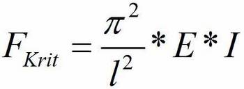
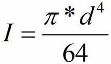
In our application, we are dealing with the second Euler buckling , so the critical buckling force can be calculated with the following formula:
When we compare the calculated value with the result at operating pressure, we can establish the following: the required piston diameter at operating pressure is larger than the piston diameter at buckling force. In this application, the operating pressure would be too high rather than there being a risk of buckling. As we are using a relatively short cylinder here, this result was to be expected. The situation is different with our column lifts, for example. Some of the cylinders used there have an effective stroke of several metres. Here it is no longer the operating pressure that is decisive, but the maximum permissible buckling force of the cylinder.
In practice, we would now take the larger of the two piston diameters (i.e. 68.9 mm in this case) and use it to select the appropriate cylinder. Of course you will not find a cylinder with an exact diameter of 68.9 mm. Instead, you select the next largest standard piston diameter that the manufacturer can supply.
In addition, the manufacturer will also be interested in other data so that he can design the cylinder, for example:
- The purpose of use to allow him to estimate the load
(e.g. strong pressure peaks, high dynamics, etc.) - The retraction and extension speed
(end position damping may be required, etc.) - The temperature at the place of use
(to select the sealing material, ...) - ...





Comments (0)
No comments found!