Most of our underground lifts are used outdoors, so the question of how to prevent water from entering the shaft and then having to be pumped out of the pit comes up time and again. Unfortunately not an easy problem to solve ...
All outdoor installations have the same problem They are exposed to the weather. This is why IP65 electrics and hot-dip galvanising are standard for us in outdoor areas.
A system that is installed in a shaft or in a pit has one more problem. Rain and snow get into the shaft or pit and must be pumped out from the bottom of the pit. This is usually not a problem with loading lift tables . After all, the maximum depth is around half a metre, so that the natural slope can often be used for drainage.
With an underground lift the situation is different. After all, the underground lift is used to bring goods from the basement to street level. The bottom of the pit is therefore often another metre below the cellar floor. Natural drainage is usually not possible here, so that a pump must be provided for meltwater and rain. Apart from the running costs of a pump, this has another potential disadvantage. The pump could fail causing the shaft to fill up with water.
Completely prevent water from entering
So the objective is clear. No water may get into the shaft. First of all, this objective is not achievable. To ensure smooth operation, a gap is needed between the platform and the surrounding shaft. If you want to use the lift not only when the weather is good, the ingress of water cannot be avoided and a pump must be provided. However, you can ensure that this pump gets as little work as possible.
Rubber seal
Unfortunately, we have to reject one of the most common solutions here. We regularly receive the suggestion to provide a rubber seal on the canopy and so completely prevent water from entering.
Believe me, this is a good idea in theory, but it hasn't worked in practice. Because the underground lift is used outdoors, it is not only exposed to rain and snow, but also to minus temperatures in general. Unfortunately, the rubber seals tend to freeze when the temperature drops below zero, so that they are torn off during the next lifting process.
This could be prevented if petroleum jelly is regularly rubbed into the seal in winter. But this is an activity that is often forgotten in the course of a hectic workday so that the water protection does not survive the first winter.
Securing a simple underground lift
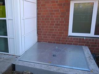
In its simplest design, the canopy does not have a surrounding edge, i.e. it cannot be paved over on site. Instead, the roof ends with a chequer plate that rests on the shaft opening.
This simple design also makes it easy to reduce water from entering the shaft. But the following combination must be selected:
- A steel plate for the canopy that is larger than the actual shaft opening
- An outdoor area that rises slightly in the direction of the shaft
- A gutter surrounding the actual canopy lift
The somewhat oversized cover closes off the entire shaft opening to prevent rain from getting into the shaft through a remaining gap. Of course this does not solve the problem of a missing seal.
This means that standing water is still a problem with this solution. To improve this situation, the outdoor area must be designed accordingly. The flow of water can already be well directed by a slightly sloping terrain, the remaining water is then drained off through a sufficiently dimensioned rain gutter.
Apart from the visual appearance, however, this solution has another disadvantage. The steel plate of the canopy rests on the shaft, which means there is a trip hazard of 6-10 mm. If the canopy is in a high traffic area, this can be a problem.
If a solution flush with the ground level is preferred, a tray-like surface should be created that is similar in design to that of an underground lift with a paved surface
Securing an underground lift covered with paving
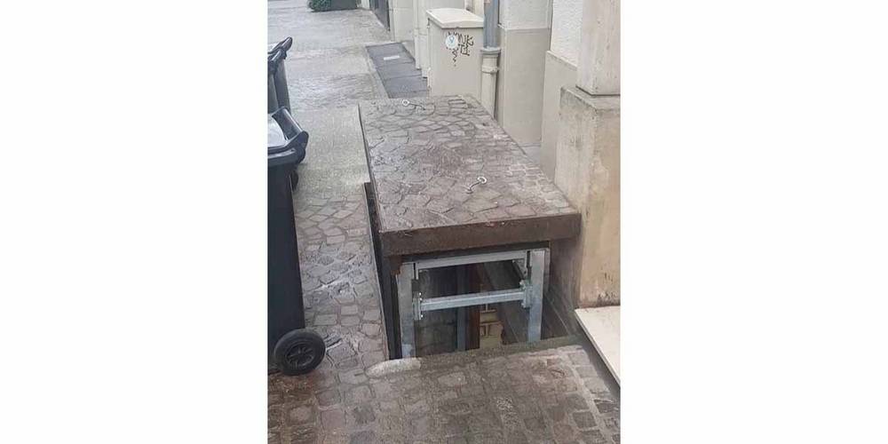
The cover of a canopy should often not be conspicuous, therefore a version is chosen which allows the laying of on-site paving. In the lowered position, only the edging of the canopy and the shaft opening is visible and one comes very close to the ideal of the "invisible" helper for the transport of goods.
However, this nicer appearance comes at the price of more complex protection against water penetration. Let us assume, for example, that the paving will be eight centimetres thick. Then the canopy will be just under 10-11 centimetres thick (8 cm of paving + granulate layer + steel plate thickness of the canopy).
A solution as in the previous section is therefore no longer possible, as this would result in a tripping hazard of more than ten centimetres, which would be neither inconspicuous nor traversable. For this reason, a seat must be created for the canopy inside the shaft head. This means that the canopy rests on the shaft in its lowered position and a matching recess creates a level surface.
Sealing the paved area
The first step is to waterproof the paved area to prevent the canopy from filling up with water. This prevents the water from flowing over the canopy into the shaft, but to the edge of the canopy.
A recessed gutter
For technical reasons, a gap must remain between the actual canopy and the surrounding courtyard. Unfortunately, water from the courtyard and also from the actual canopy surface now flows into this gap.
Although the ingress of water from the yard can be minimised again by a sloping terrain and a gutter in front of it, this does not always allow the water to be completely drained off and there is still the rain that falls directly on the canopy.
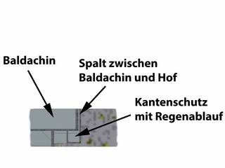
For this reason, we not only recommend creating a seat for the canopy, but to also integrate a gutter in this seat. This means that a pit edge protection with an integrated gutter is installed (see the image 'Pit edge protection with gutter’) before the actual installation of the underground lift.
Now although some of the water flows into the gap between the canopy and the courtyard, it is immediately drained off again via the integrated gutter and does not reach the shaft pit, where it would have had to be pumped out at great expense.
The remaining problem area
Unfortunately, the recessed gutter is only successful on three sides. The loading edge still poses a problem. If one would create an equally large seat for the canopy here, the user would have a problem.<br/> This would create a gap of about 10 cm wide and 10 cm deep between the yard surface and the platform of the lift table when it is in the raised position. This size gap is too wide to be bridged with most means of transport for this purposes. This means that the wheels of a flat-bed cart, a wire-mesh trolley or even a pallet truck would get stuck making safe and convenient loading and unloading impossible.
One solution would be to bridge this gap with ramp plates or the like. However, from practical experience we know that this solution is not very popular with the user due to the additional work steps involved and that a larger gap should therefore be avoided.<br/> For the loading side, we therefore again recommend reducing the water ingress by means of a correspondingly sloping terrain and a strategically placed gutter. The remaining water must continue to be pumped out from the bottom of the pit.
Conclusion
The first step in the protection of the shaft begins with an appropriate design of the courtyard. A large amount of water can already be drained off if the courtyard is designed with an appropriate slope and a gutter is strategically placed in front of the actual hydraulic lift .
However, one-hundred per cent protection against water ingress does not exist, which is why a drainage option must be provided in the shaft pit for every underground lift.


Comments (0)
No comments found!