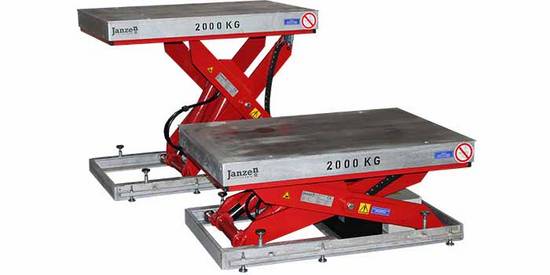
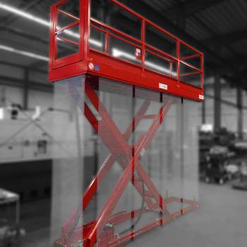
100% quality control
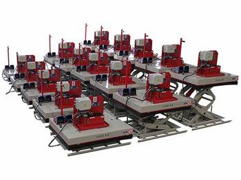
Whether you order one or twenty hydraulic lift tables is not crucial: Each single lift table is subjected to a strict test.
Enquire about the most common variants
Get a free quote for your hydraulic lift table in just two steps. Feel free to note any customizations, such as a different payload or dimensions, in the 'Change requests' field:
What advantages do our hydraulic lift tables offer?
In times of increasing cost pressures, economic solutions are in demand. In this regard, hydraulic lift tables offer a significant advantage: they are cost-effective. Our modular system helps to save costs and shorten design phases by utilizing standardized components.
Additional advantages of hydraulic scissor lift tables include:
- High power transmission: Loads of several tons can be moved effortlessly.
- Flexible customization options: Lift tables are extremely versatile in their applications.
- Stepless height adjustment: Promoting ergonomics in the workplace and increasing flexibility.
- Space-saving in limited spaces: Scissor lift tables can be designed to be passable, making them ideal for confined spaces.
- Durability: Thanks to their robust and stable construction, our lift tables are reliable partners in demanding industrial applications.
Furthermore, we place great emphasis on a low-maintenance design, allowing our lift table to be maintained with relatively little effort. A detailed overview of the required maintenance tasks can be found in our article: 'Maintenance work on a scissor lift table'.
If you would like to learn more about the pros and cons of hydraulic lift tables, we recommend reading our article: 'Hydraulic lift tables: pros & cons'.
What configurations are possible?
Our product range goes beyond standard lift tables. As a lift table manufacturer, we have the capability to offer customized solutions tailored to your specific requirements.
This means that we can adjust not only the platform dimensions but also the lifting heights flexibly. Lifting speeds of up to 80 mm per second and load capacities ranging from 500 to 16,000 kg pose no challenge for us. Additionally, our lift tables can be equipped with various accessories and different control options, making them highly versatile.
It's also worth mentioning our adaptability in choosing hydraulic fluids. For instance, in water protection areas, we use environmentally friendly fluids instead of mineral oil, or for the food industry, we use food-grade oil.
How does a hydraulic lift table work?
In the following video, we explain the functionality of a hydraulic lift table, covering the lifting movement, secure load holding, and the lowering movement.
Please note:
While we demonstrate the operation on a hydraulic scissor lift table, the principle applies to all types of lift tables. The various designs only differ in the type of drive unit used.
The lifting movement
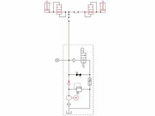
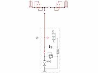
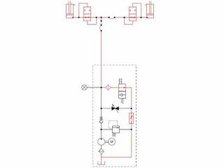
A brief note beforehand: For illustration, alongside our explanations, you will find a section from a hydraulic diagram of a simple lift table. In this diagram, we've marked the path that the hydraulic oil takes during the different phases.
The lifting movement begins with the activation of an electric motor. This electric motor drives a small gear pump that moves the oil from the tank into the hydraulic circuit of the lift table.
The gear pump is connected to the cylinders of the lift table through hydraulic hoses. This allows the oil to flow directly from the pump to the hydraulic cylinders. The incoming oil causes the piston rod to extend from the cylinder tube (the active components are shown in red).
As one end of the cylinder is connected to the inner scissor and the other end to the outer scissor, the scissor spreads apart with the cylinders: The platform with the load on it is raised.
Holding the load at the desired lifting height
Once the desired lifting position is reached, check valves ensure that the hydraulic oil is retained in the cylinders and does not flow back into the tank. The lift table remains in the current position.
In the hydraulic diagram, we have highlighted the main check valve in red. As evident in the hydraulic diagram, there is also a check valve in the path of the lowering valve (in green), preventing the oil in the cylinders from moving.
The lowering movement
For the lowering movement of hydraulic scissor lift platforms, the drive is typically not required. Instead, the platform's own weight is sufficient to cause the cylinders to retract.
To achieve this, the lowering valve is opened (see the graphic). This clears the path for hydraulic oil, allowing it to flow from the cylinders back into the tank. The cylinders retract, and the platform lowers with the load.
To ensure that the lowering speed of the lift table does not become too high, a lowering speed control valve is installed in the hydraulic line. This valve limits the maximum flow rate, preventing the desired lowering speed from being exceeded.
Applications for hydraulic lift tables
With the exception of elevating work platforms, our lift tables are designed for the sole purpose of transporting loads. They are versatile and applicable in various settings, including production, warehouses, workshops, theaters, and outdoor environments. Here is a brief overview of potential use cases:
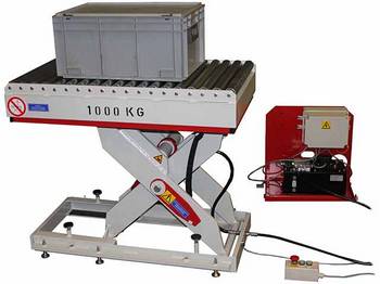
Work lift tables as assembly aid in an industrial hall or workshop
For workplaces where your employees frequently handle heavy loads, our work lift table prove to be valuable assistants. They contribute to the ergonomic design of workplaces and facilitate various tasks, such as assembly, repairs, or packaging.
Depending on your requirements, we offer both stationary lift tables and mobile lift tables to meet different operational needs.
Loading lift tables for material handling
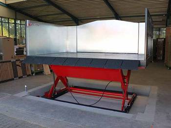
Loading lift tables are specifically designed for loading and unloading vehicles. They are often positioned outdoors, making a galvanized construction highly recommended.
To facilitate the loading and unloading process, these loading platforms typically come equipped with loading flaps. Guardrails and portals are installed to prevent individuals from falling off the platform during the transfer of goods.
Goods lifts for transporting goods between multiple levels
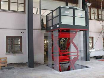
When it comes to transporting bulky and heavy loads across multiple levels, our goods lifts are the ideal choice. They are not only used in warehouses and production halls but also find applications in hotels, laundries, and theaters among our clientele.
A specific use case is the underground lift. This type of lift is particularly useful when goods need to be recessed into the floor for protection, aesthetic reasons, or storage purposes.
Elevating work platforms - safe working at heights
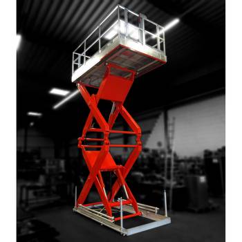
The elevating work platform is somewhat a special case in our product portfolio. It is the only type of lift table in our range where passenger transport is permitted.
Primarily, elevating work platforms are used to provide employees with a safe working environment at heights, especially when heavy tools or equipment are required.
Frequently asked questions & our answers ...
Where is the headquarters of Janzen Lifttechnik GmbH?
We are at home in the beautiful Emsland, more precisely in Niederlangen a member community of the joint community Lathen directly on the A31 motorway. This means that we are roughly halfway between North Rhine-Westphalia and the North Sea, right on the Dutch border.
Our region is known, among other things, for the various nature reserves, the well-developed cycle paths, the manufacture of cruise ships, as well as the headquarters of various distilleries.
Should you ever come to our region, we look forward to a visit in our plant.
Where are the lift tables and lifts produced?
With us, not only does the final assembly take place in Germany, but we also cover the entire production chain from construction through steel construction to final assembly in our plant in Niederlangen. With us you get a real 'Made in Germany'.
Is the offer aimed only at traders or also at private individuals?
Even if our products are mainly used in an industrial environment, we naturally also offer them to private individuals.
Just give us a call or send us an enquiry and we will be happy to contact you.
Will I receive a drawing before production starts?
In any case. To ensure that you get the product that you really want, we provide you with an approval drawing before production begins. In addition to the actual product, this also includes the installation situation. As the saying goes, a picture is worth a thousand words.
Can I get a CAD model?
After ordering and the design phase, we are pleased to provide you with CAD models. Data exchange is possible in all common formats, including .stp, .dxf, .dwg, etc.
Where can delivery of the products be made?
We produce our lift tables and column lifts in accordance with European standards and guidelines. Accordingly, our sales area is limited to all countries that recognize these standards and guidelines (e.g. the members of the European Union, Switzerland and Australia).
For which countries is the assembly service available?
On request, we assemble our systems throughout Germany, as well as in the neighboring countries of Germany.

